
Sonar tutorial
People have been fishing for thousands of years. Every person fishing has had the same problem - finding fish and getting them to bite. Although sonar can’t make the fish bite, it can solve the problem of finding fish. You can’t catch them if you’re not fishing where they are - and the Lowrance sonar will prove it.In the late 1950s, Carl Lowrance and his sons Arlen and Darrell began scuba diving to observe fish and their habits. This research, substantiated by local and federal government studies, found that about 90 percent of the fish congregated in 10 percent of the water on inland lakes. Their dives confirmed that most species of fish are affected by underwater structure (such as trees, weeds, rocks, and drop-offs), temperature, current, sunlight and wind. These and other factors also influence the location of food (baitfish, algae and plankton). Together, these factors create conditions that cause frequent relocation of fish populations.
Out of this simple beginning, a new industry was formed in 1957 with the sale of the first transistorized sportfishing sonar. In 1959, Lowrance introduced “The Little Green Box,” which became the most popular sonar instrument in the world. Lowrance has come a long way since 1957. From “little green boxes” to the latest in sonar and GPS technology, Lowrance continues to lead in the world of sportfishing sonar.
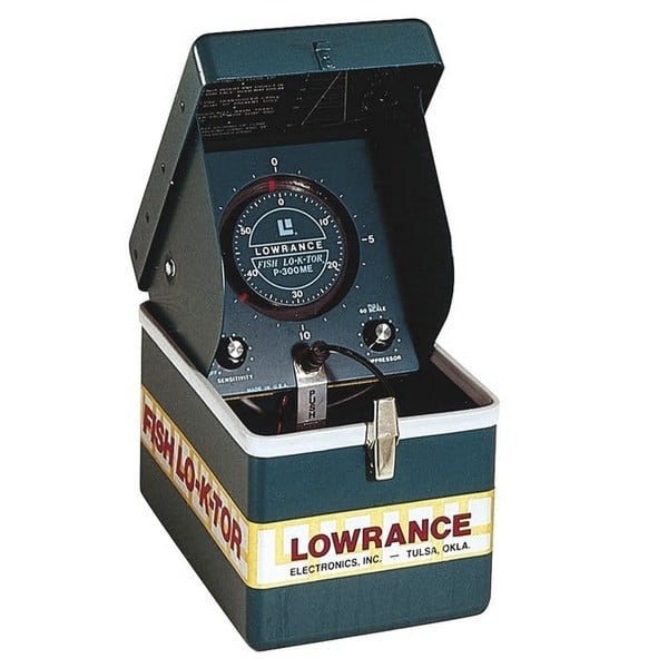 “The Little Green Box”
How it works?
The word "sonar" is an abbreviation for "SOund, NAvigation and Ranging." It was developed as a means of tracking enemy submarines during World War II. A sonar consists of a transmitter, transducer, receiver and display.In the simplest terms, an electrical impulse from a transmitter is converted into a sound wave by the transducer and sent into the water. When this wave strikes an object, it rebounds. This echo strikes the transducer, which converts it back into an electric signal, which is amplified by the receiver and sent to the display. Since the speed of sound in water is constant (approximately 4800 feet per second), the time lapse between the transmitted signal and the received echo can be measured and the distance to the object determined. This process repeats itself many times per second.
The frequencies most often used in Lowrance sonar are 192 - 200 kHz (kilohertz); they also make some units that use 50 kHz. Although these frequencies are in the sound spectrum, they’re inaudible to both humans and fish. (You don’t have to worry about the sonar unit spooking the fish - they can’t hear it.)
As mentioned earlier, the sonar unit sends and receives signals, then “prints” the echo on the display. Since this happens many times per second, a continuous line is drawn across the display, showing the bottom signal. In addition, echoes returned from any object in the water between the surface and bottom are also displayed. By knowing the speed of sound through water (4800 feet per second) and the time it takes for the echo to be received, the unit can show the depth of the water and any fish in the water.
Total system performance
There are four facets to a good sonar unit:- High power transmitter
- Efficient transducer
- Sensitive receiver
- High resolution/contrast display
Lowrance calls this "Total System Performance" specification. All of the parts of this system must be designed to work together, under any weather condition and extreme temperatures.
High transmitter power increases the probability that you will get a return echo in deep water or poor water conditions. It also lets you see fine detail, such as bait fish and structure.
The transducer must not only be able to withstand the high power from the transmitter, but it also has to convert the electrical power into sound energy with little loss in signal strength. At the other extreme, it has to be able to detect the smallest of echoes returning from deep water or tiny bait fish.
The receiver also has an extremely wide range of signals it has to deal with. It must dampen the extremely high transmit signal and amplify the small signals returning from the transducer. It also has to separate targets that are close together into distinct, separate impulses for the display.
The display must have high resolution (vertical pixels) and good contrast to be able to show all of the detail crisply and clearly. This allows fish arches and fine detail to be shown.

Frequency
Most Lowrance sonar units today operate at 192 or 200 kHz (kilohertz), with a few using 50 kHz.There are advantages to each frequency, but for almost all freshwater applications and most saltwater applications, 192 or 200 kHz is the best choice. It gives the best detail, works best in shallow water and at speed, and typically shows less "noise" and undesired echoes. Target definition is also better with these higher frequencies. This is the ability to display two fish as two separate echoes instead of one "blob" on the screen.
There are some applications where a 50 kHz frequency is best. Typically, a 50 kHz sonar (under the same conditions and power) can penetrate water to deeper depths than higher frequencies. This is due to water's natural ability to absorb sound waves. The rate of absorption is greater for higher frequency sound than it is for lower frequencies. Therefore, you'll generally find 50 kHz used in deeper saltwater applications. Also, 50 kHz transducers typically have wider coverage angles than 192 or 200 kHz transducers. This characteristic makes them useful in tracking multiple downriggers. Thus, even when these downriggers are in relatively shallow depths, 50 kHz is preferred by many fishermen. In summary, the differences between these frequencies are:
192 or 200 kHz
- Shallower depths
- Narrow cone angle
- Better definition and target separation
- Less noise susceptibility
50 kHz
- Deeper depths
- Wide cone angle
- Less definition and target separation
- More noise susceptibility
Transducers
The transducer is the sonar unit's "antenna." It converts electric energy from the transmitter to high frequency sound. The sound wave from the transducer travels through the water and bounces back from any object in the water. When the returning echo strikes the transducer, it converts the sound back into electrical energy which is sent to the sonar unit's receiver. The frequency of the transducer must match the sonar unit's frequency. In other words, you can't use a 50 kHz transducer or even a 200 kHz transducer on a sonar unit designed for 192 kHz! The transducer must be able to withstand high transmitter power impulses, converting as much of the impulse into sound energy as possible. At the same time, it must be sensitive enough to receive the smallest of echoes. All of this has to take place at the proper frequency and reject echoes at other frequencies. In other words, the transducer must be very efficient.Crystal
The active element in a transducer is a man-made crystal (lead zirconate or barium titanate). To make these crystals the chemicals are mixed, then poured into molds. These molds are then placed in an oven which "fires" the chemicals into the hardened crystals. Once they've cooled, a conductive coating is applied to two sides of the crystal. Wires are soldered to these coatings so the crystal can be attached to the transducer cable. The shape of the crystal determines both its frequency and cone angle. For round crystals (used by most sonar units), the thickness determines its frequency and the diameter determines the cone angle or angle of coverage (see Cone Angles section). For example at 192 kHz, a 20 degree cone angle crystal is approximately one inch in diameter, whereas an eight degree cone requires a crystal that is about two inches in diameter. That's right. The larger the crystal's diameter - the smaller the cone angle. This is the reason why a twenty degree cone transducer is much smaller than an eight degree one - at the same frequency.Housings
Transducers come in all shapes and sizes. Most transducers are made from plastic, but some thru-hull transducers are made from bronze. As shown in the previous section, frequency and cone angle determine the crystal's size. Therefore, the transducer's housing is determined by the size of the crystal inside.Speed and the Transducer
Cavitation is a major obstacle to achieving high speed operation. If the flow of water around the transducer is smooth, then the transducer sends and receives signals normally. However, if the flow of water is interrupted by a rough surface or sharp edges, then the water flow becomes turbulent. So much so that air becomes separated from the water in the form of bubbles. This is called "cavitation." If these air bubbles pass over the face of the transducer (the part of the housing that holds the crystal), then "noise" is shown on the sonar unit's display. You see, a transducer is meant to work in water - not air. If air bubbles pass over the transducer's face, then the signal from the transducer is reflected by the air bubbles right back into it. Since the air is so close to the transducer, these reflections are very strong. They will interfere with the weaker bottom, structure, and fish signals, making them difficult or impossible to see.The solution to this problem is to make a transducer housing that will allow the water to flow past it without causing turbulence. However, this is difficult due to the many constraints placed upon the modern transducer. It must be small, so that it doesn't interfere with the outboard motor or its water flow. It must be easy to install on the transom so that a minimum of holes need to be drilled. It must also "kick-up" without damage if struck by another object. Again, the patented design of the HS-WS transducer is Lowrance's latest improvement in high-speed transducer technology. It combines high speed operation with easy installation and will "kick-up" if struck by an object at high speed.
The cavitation problem is not limited to the shape of the transducer housing. Many boat hulls create air bubbles that pass over the face of a transom mounted transducer. Many aluminum boats have this problem due to the hundreds of rivet heads that protrude into the water. Each rivet streams a river of air bubbles behind it when the boat is moving, especially at high speed. To fix this problem, mount the face of the transducer below the air bubbles streaming from the hull. This typically means you have to mount the transducer's bracket as far down as possible on the transom.
Transducer Cone Angles
The transducer concentrates the sound into a beam. When a pulse of sound is transmitted from the transducer, it covers a wider area the deeper it travels. If you were to plot this on a piece of graph paper, you would find that it creates a cone shaped pattern, hence the term "cone angle." The sound is strongest along the center line or axis of the cone and gradually diminishes as you move away from the center.In order to measure the transducer's cone angle, the power is first measured at the center or axis of the cone and then compared to the power as you move away from the center. When the power drops to half (or -3db[decibels] in electronic terms), the angle from that center axis is measured. The total angle from the -3db point on one side of the axis to the -3db point on the other side of the axis is called the cone angle.
This half power point (-3db) is a standard for the electronics industry and most manufacturers measure cone angle in this way, but a few use the -10db point where the power is 1/10 of the center axis power. This gives a greater angle, as you are measuring a point further away from the center axis. Nothing is different in transducer performance; only the system of measurement has changed. For example, a transducer that has an 8 degree cone angle at -3db would have a 16 degree cone angle at -10db.
Although the half power point is the standard for measuring cone angles, fish detection angles are much larger. Lowrance sonar units have very sensitive receivers and can detect return echoes from fish, structure or the bottom out to 60° or more. This means that the fish detection angle is 60° even though the cone angle is only 20°.

20 degree cone angle | 8 degree cone angle
Lowrance offers transducers with a variety of cone angles. Wide cone angles will show you more of the underwater world, at the expense of depth capability, since it spreads the transmitter's power out. Narrow cone angle transducers won't show you as much of what's around you, but will penetrate deeper than the wide cone. The narrow cone transducer concentrates the transmitter's power into a smaller area. A bottom signal on the sonar unit's display will be wider on a wide cone angle transducer than on a narrow one because you are seeing more of the bottom. The wide cone's area is much larger than the narrow cone.High frequency (192 - 200 kHz) transducers come in either a narrow or wide cone angle. The wide cone angle should be used for most freshwater applications and the narrow cone angle should be used for all saltwater applications. Low frequency (50 kHz) sonar transducers are typically in the 30 to 45 degree range. Although a transducer is most sensitive inside its specified cone angle, you can also see echoes outside this cone; they just aren't as strong. The effective cone angle is the area within the specified cone where you can see echoes on the display. If a fish is suspended inside the transducer's cone, but the sensitivity is not turned up high enough to see it, then you have a narrow effective cone angle. You can vary the effective cone angle of the transducer by varying the receiver's sensitivity. With low sensitivity settings, the effective cone angle is narrow, showing only targets immediately beneath the transducer and a shallow bottom. Turning the sensitivity control up increases the effective cone angle, letting you see targets farther out to the sides.
Water and Bottom Conditions
The type of water you're using the sonar in affects its operation to a large degree. Sound waves travel easily in a clear freshwater environment, such as most inland lakes.In salt water however, sound is absorbed and reflected by suspended material in the water. Higher frequencies are most susceptible to this scattering of sound waves and can't penetrate salt water nearly as well as lower frequencies. Part of the problem with salt water is that it's a very dynamic environment - the oceans of the world. Wind and currents constantly mix the water. Wave action creates and mixes air bubbles into the water near the surface, which scatters the sonar signal. Micro-organisms, such as algae and plankton, scatter and absorb the sonar signal. Minerals and salts suspended in the water do the same thing. Fresh water also has wind, currents and micro-organisms living in it that affect the sonar's signal - but not as severely as salt water.
Mud, sand and vegetation on the bottom absorb and scatter the sonar signal, reducing the strength of the return echo. Rock, shale, coral and other hard objects reflect the sonar signal easily. You can see the difference on your sonar's screen. A soft bottom, such as mud, shows as a thin line across the screen. A hard bottom, such as rock, shows as a wide line on the sonar's screen.

Soft Bottom | Hard Bottom
You can compare sonar to using a flashlight in a dark room. Moving the light around the room, it's easily reflected from white walls and bright, hard objects. Moving the light onto a darkly carpeted floor returns less light because the dark color of the carpet absorbs the light, and the rough texture scatters it, returning less light to your eyes. Adding smoke to the room (children, don't try this at home!), you'll see even less. The smoke is equivalent to salt water's effect on the sonar signal.Water Temperature and Thermoclines

